
From Retail Design Concept to a Curved Illuminated Storefront
A real retail engineering project showing how a continuous curved illuminated storefront concept was developed from design intent into structural details, manufacturing references, site installation and a completed commercial retail feature.
More Than a Finished Storefront
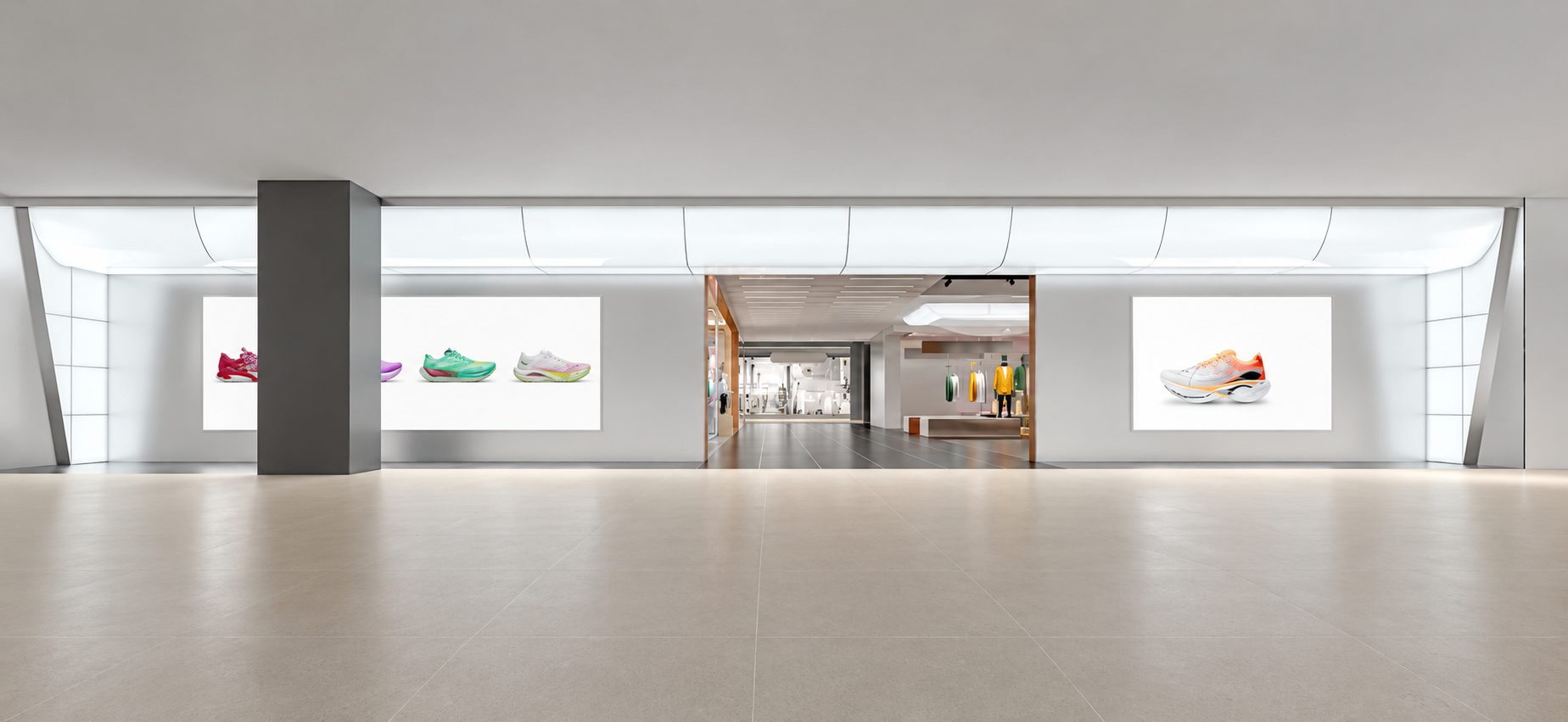
The finished storefront appears simple: a clean, continuous illuminated architectural feature following the geometry of the retail entrance. Behind that visual result was a much more complex development process involving design interpretation, structural development, manufacturing translation and site coordination.
The Design Defined the Look. Engineering Had to Define the Build.
The original retail concept called for a continuous illuminated feature following the storefront geometry. Visually, the surface needed to read as one clean architectural element rather than a collection of unrelated components.
A design rendering can communicate the intended appearance, but it does not automatically define the supporting structure, component relationships, lighting position, connection method or practical installation sequence.
The engineering task was therefore not to redesign the visual concept. It was to preserve that concept while developing a physical structure capable of producing the intended result.
One Continuous Visual Surface. Multiple Technical Relationships.
The challenge was not simply producing a curved component. The illuminated surface, supporting layers, curved geometry, connection details and site conditions all had to work together while protecting the intended retail appearance.
Curved Geometry
Translate the visual curve into defined geometry that could be referenced during component development, production and installation.
Layered Construction
Coordinate the visible surface with the supporting construction rather than treating the illuminated face as an isolated component.
Lighting Integration
Allow the lighting system to work within the available structure while maintaining the intended illuminated appearance.
Site Integration
Develop the feature around the realities of the storefront substrate, fixing points, edge conditions and installation sequence.
Turning the Visual Concept Into a Buildable Structure
Once the visual intent was understood, the project moved into engineering development. The storefront feature was broken down into coordinated construction relationships.
The engineering process considered how the visible surface, curved profile, support structure, lighting and connection details would work together.
Establish the curved profile and dimensional relationships.
Separate the continuous feature into practical construction layers.
Coordinate the illuminated surface with the supporting structure.
Define how components meet, align and transition at critical areas.
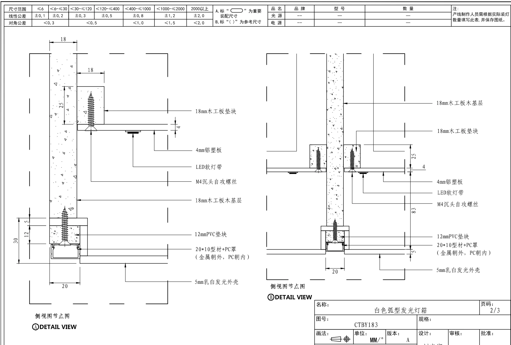
One Visual Feature Became a Coordinated Construction System
Detailed drawings were used to define how the curved illuminated surface related to its supporting construction, lighting position, fixing conditions and section transitions before the project moved further toward physical execution.
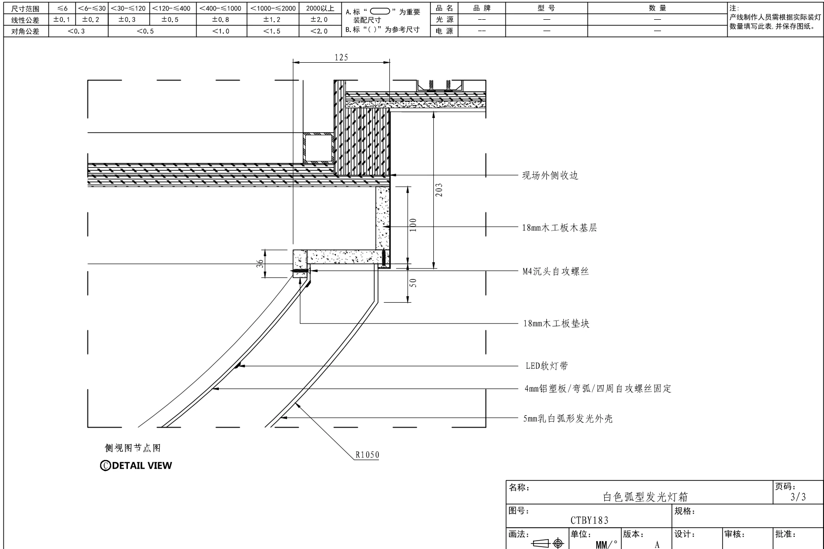
One visual surface.
Multiple coordinated components.
This is where custom retail manufacturing moves beyond straightforward fabrication. The finished customer-facing surface depends on the relationship between geometry, structure, material, lighting, connection details and the surrounding site conditions.
Engineering Information Had to Become Production Information
A project is not manufacturing-ready simply because the overall structure has been defined. Engineering intent still has to be translated into information that production teams can use consistently and into components that will work together as one finished system.
Component Consistency
Individual sections had to maintain the intended geometry so adjoining components could form a continuous visual line.
Assembly Relationships
Connections between manufactured components needed to reflect the engineering logic established during development.
Surface Continuity
Production decisions had to protect the clean customer-facing appearance of the illuminated architectural feature.
Installation Readiness
Manufactured sections needed to correspond with the intended installation sequence and actual project conditions.
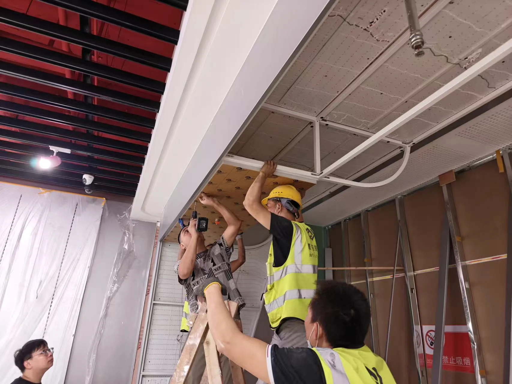
Engineering Has to Survive the Transition to Installation
A technically correct drawing is only useful when the developed structure can also be understood and assembled in the real project environment.
The installation stage connected the engineering work with the actual storefront, where the curved feature, supporting construction and surrounding architectural elements had to come together physically.
Connect the developed structure with the actual retail environment.
Confirm how developed sections meet and align during installation.
Coordinate the feature with surrounding architectural elements.
Protect the continuous architectural appearance through installation.
From Design Intent to a Real Commercial Environment
The completed storefront shows the final visual result: a continuous curved illuminated feature integrated into the retail environment. But the finished photograph represents only the final stage of the project. The real value lies in the development path behind it.
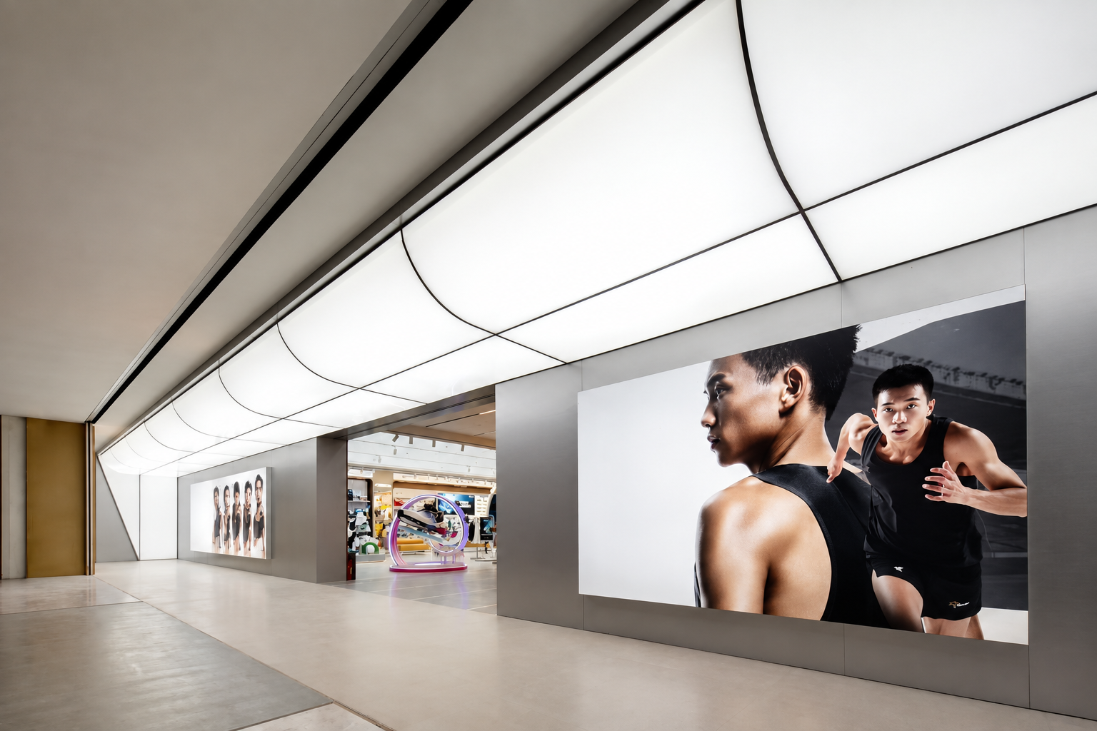
The intended retail appearance was translated into practical technical requirements.
Geometry, supporting construction and component relationships were defined.
Engineering information was translated toward practical component manufacturing.
The developed structure was carried into the real retail environment.
The final feature retained the continuous illuminated storefront expression.
The Capability Is Not Just Fabrication
Real custom retail projects frequently begin with a concept rendering, store drawing, CAD reference, prototype, sample or incomplete technical package. The missing step is turning that information into something that can actually be manufactured and installed.
Design Interpretation
Understand the visual intent before defining the manufacturing solution.
Engineering Development
Identify the technical relationships required to turn concept into structure.
Structural Breakdown
Translate a continuous feature into coordinated construction components.
Curved Component Development
Develop geometry and construction relationships around non-standard forms.
Lighting Integration
Consider the illuminated surface together with its supporting construction.
Production Drawing Development
Convert engineering decisions into references that support manufacturing.
Manufacturing Coordination
Ensure individual components work as parts of the complete physical system.
Site Installation Coordination
Connect the developed solution with real project and installation conditions.
Your Project Does Not Have to Be Production-Ready Yet
Custom projects can begin from different levels of information. GREAT ACRYLICS can review the design from the perspective of structure, materials, manufacturing feasibility, component development and practical production.
Have a Design That Needs to Become Buildable?
Send us your retail concept, CAD drawing, store drawing, reference image or existing sample. We can review the structure, materials, manufacturing feasibility and practical development path.