
From Design Concept to a Custom Illuminated Ceiling Feature
A real commercial project showing how an unconventional illuminated ceiling concept was developed through internal structural discussion, engineering drawings, metal frame development, fabrication and final installation.
The Design Showed the Form. It Did Not Yet Define the Structure.
The original visual concept established a strong architectural direction: suspended illuminated forms that would become a visible feature within the commercial interior.
But a rendering alone does not explain how the feature should be supported, how its geometry should be controlled, how the internal frame should be assembled, or how lighting and outer surfaces should work together.
Before fabrication could begin, the visual idea had to be translated into a practical construction system.
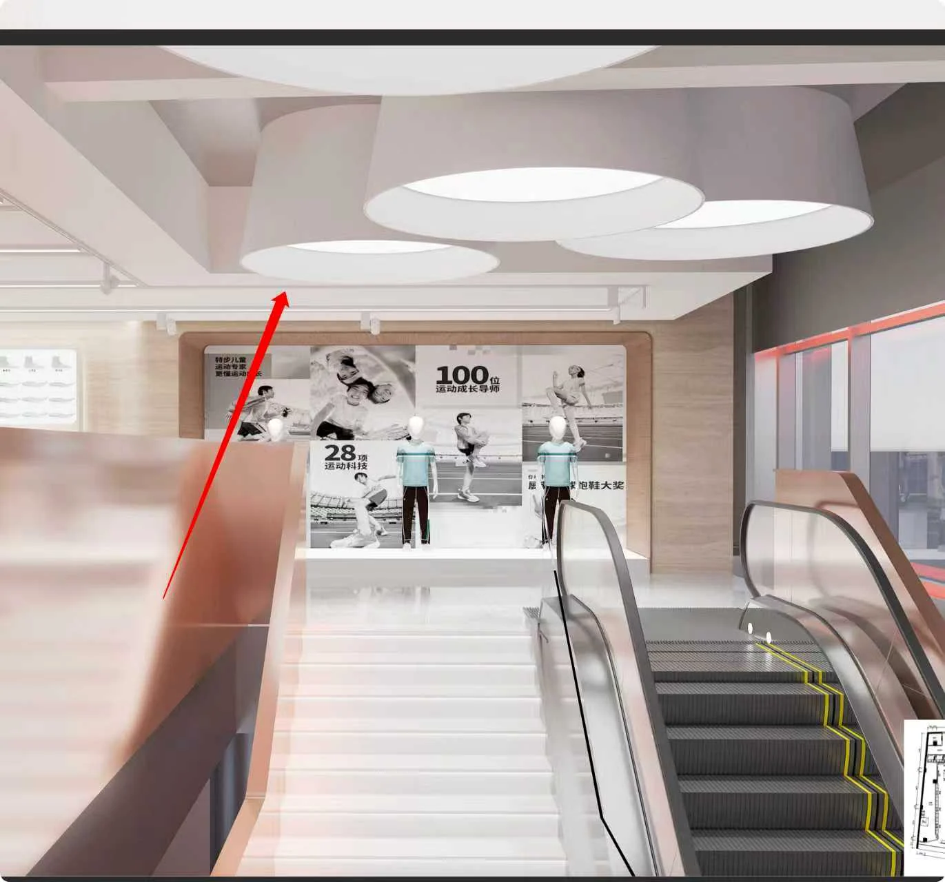
A Strong Visual Concept Needed a Buildable Internal Logic
The design established the overall proportion, illuminated appearance and relationship between the suspended forms and the surrounding commercial environment.
The engineering task was to preserve that visual intent while determining what needed to happen inside the feature.
A Sculptural Form Is Only the Beginning
The visible shape was only one part of the problem. The complete feature had to work simultaneously as a structure, an illuminated object and a manufacturable assembly.
Complex Geometry
The external form required controlled geometry so that the finished pieces could retain the intended visual proportion.
Internal Support
A hidden structural framework had to support the form without compromising the clean appearance of the illuminated exterior.
Lighting Integration
Lighting, frame positions and outer surfaces needed to be considered as one coordinated system rather than separate components.
Manufacturing Logic
The structure needed to be divided into practical components that could be fabricated, assembled and prepared for installation.
From Internal Discussion to Production Drawing
Before formal drawings were developed, early structural sketches were used by our team to discuss connection details, component relationships and manufacturing feasibility.
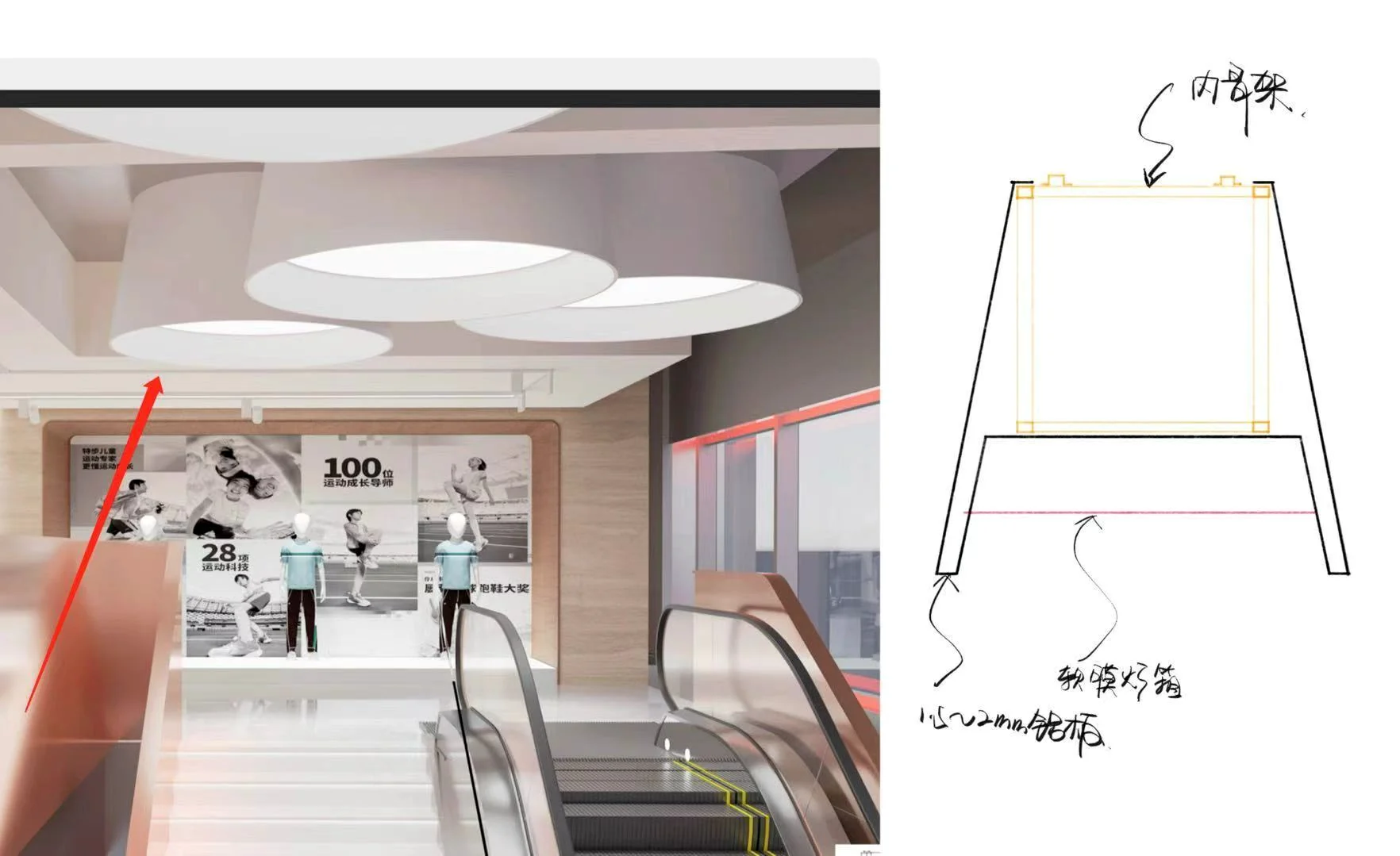
Internal Engineering Sketch
Early sketches helped the team explore how the outer form, supporting frame and internal relationships could work together before the solution was formalized.
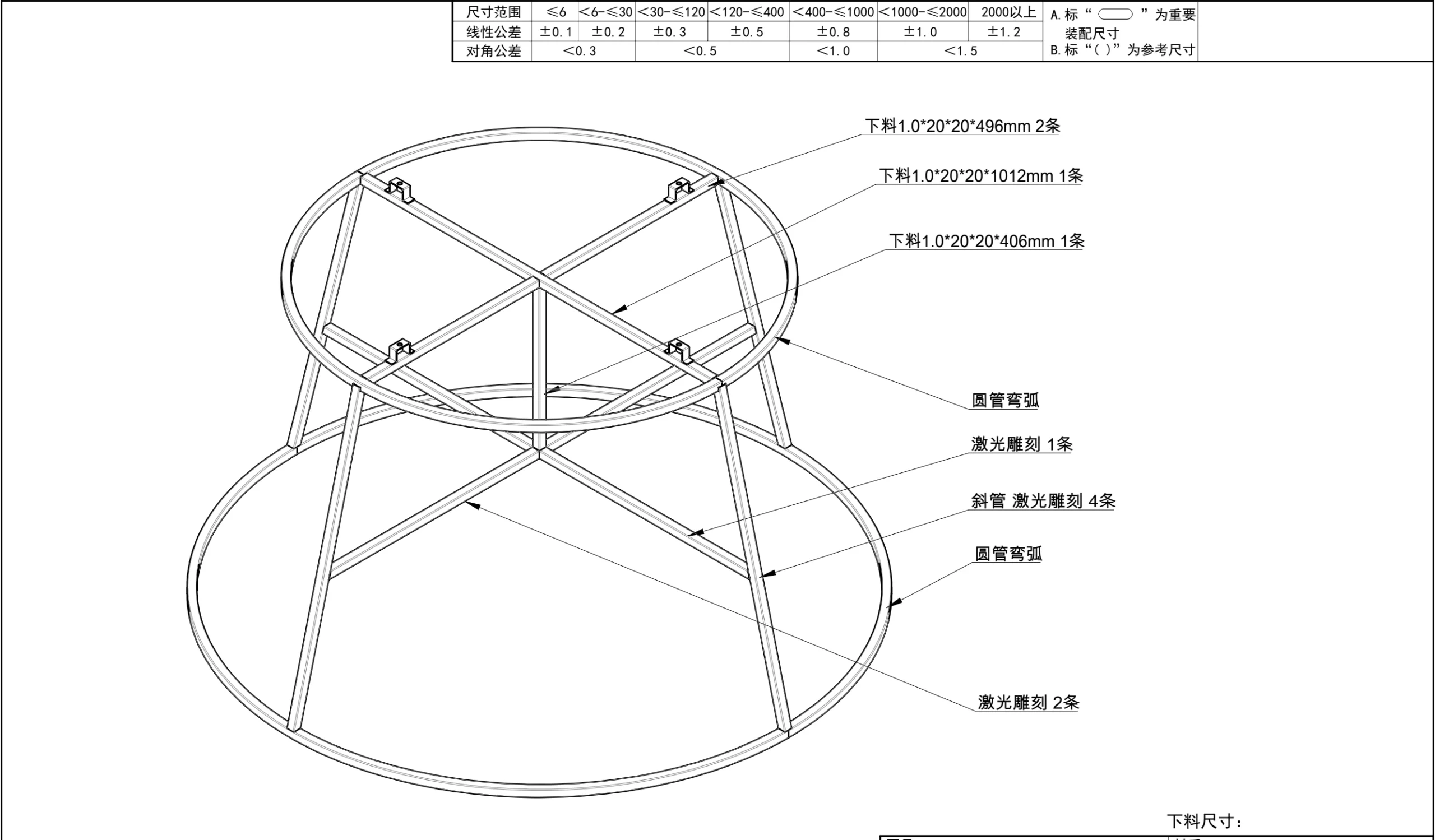
Formal Structural Development
Once the structural direction was established, the concept was translated into a more defined internal frame and component relationship for manufacturing development.
This intermediate stage is important in custom manufacturing because many commercial design concepts arrive with a clear visual objective but without a complete production-ready construction solution.
Turning the Structural Direction Into Manufacturing Information
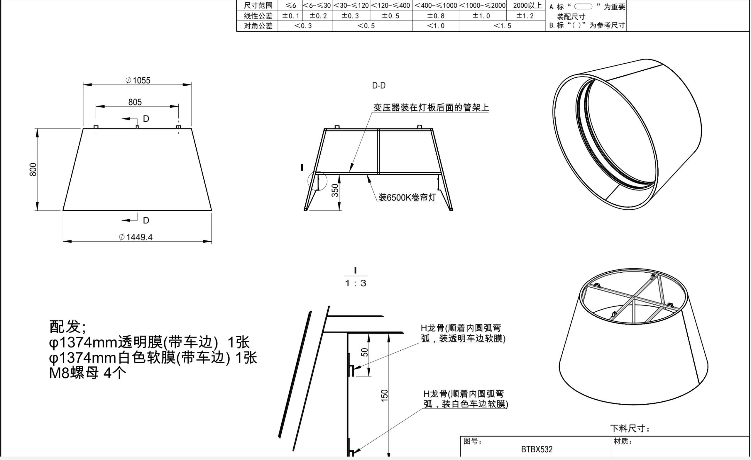
Engineering development progressively defined the internal frame, assembly relationships and overall construction logic. Each drawing answered a different part of the manufacturing problem.
Structural Framework
The internal frame established the supporting geometry and the basic structural relationship behind the visible form.
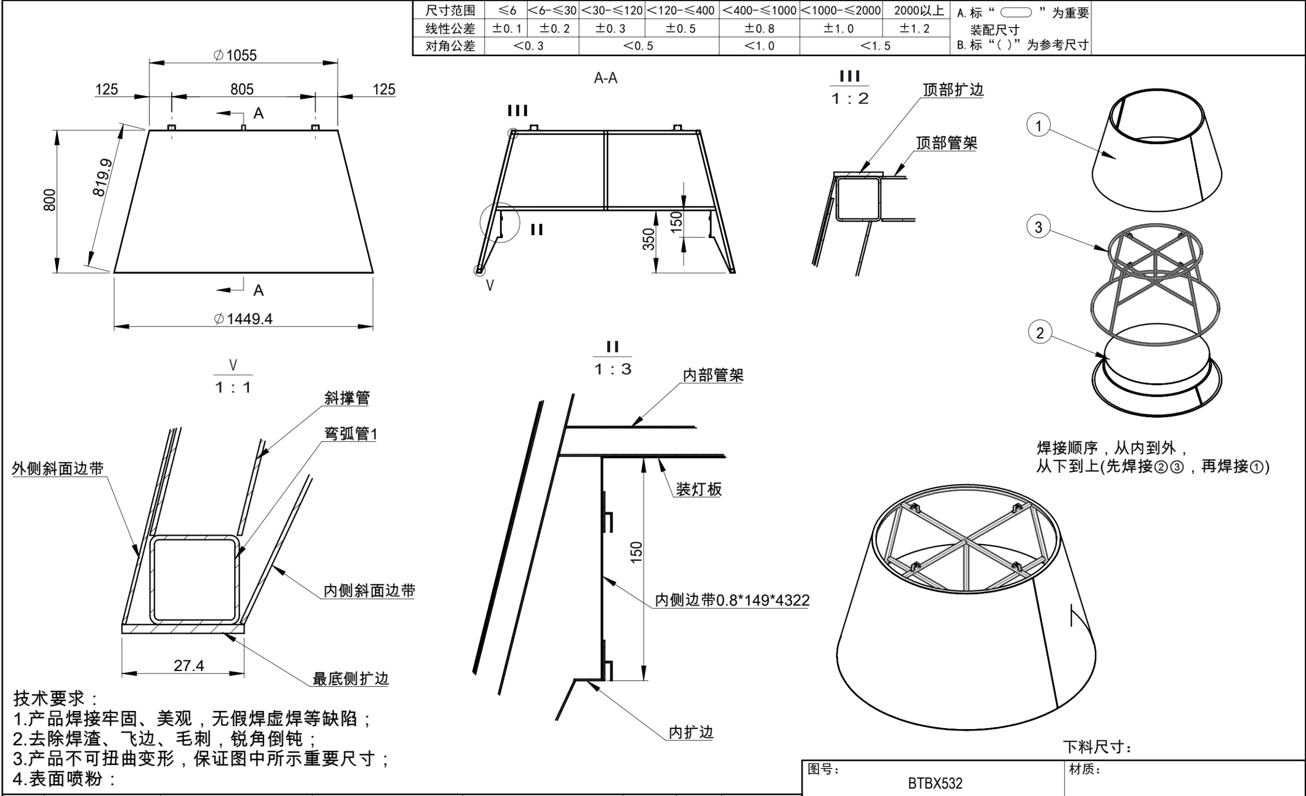
Component Relationships
Assembly drawings clarified how individual parts related to one another and how the complete feature could be constructed as a coordinated system.
Structure + Surface + Lighting
The developed solution coordinated structural elements, illuminated surfaces and internal relationships before fabrication.
The Frame, Surface and Lighting Had to Work as One System
For a custom illuminated architectural feature, structure and lighting cannot be treated as independent decisions. The position of one affects the performance, assembly and appearance of the others.
Geometry
Define the external form and establish the key proportions that control the visual result.
Metal Frame
Develop an internal supporting structure capable of holding and maintaining the intended form.
Lighting
Coordinate lighting positions with the internal structure and illuminated exterior surfaces.
Assembly
Translate the complete system into components and relationships that can move into real fabrication.
Engineering Information Had to Become a Real Metal Structure
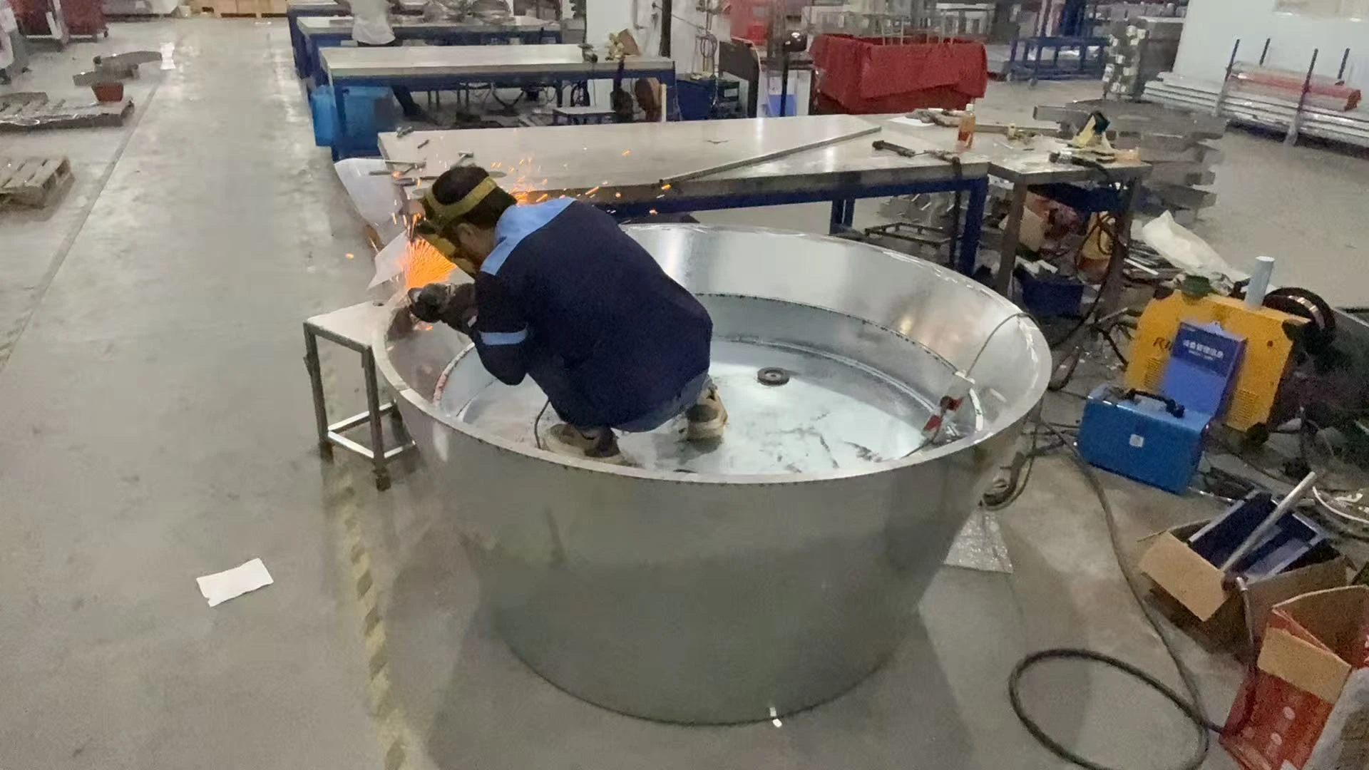
Once the engineering relationships were defined, the project moved from drawings into physical fabrication.
At this stage, geometry, frame relationships and assembly logic had to remain consistent with the developed engineering solution.
From Engineering Development to the Finished Environment
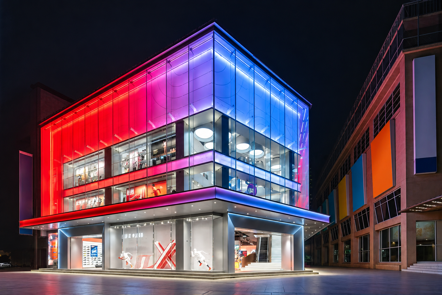
The completed installation closes the engineering loop: the original visual intent was retained while the hidden structural, manufacturing and lighting decisions made the feature possible in a real commercial environment.
The Capability Is in the Development Between Concept and Production
Custom manufacturing is not always a matter of receiving a finished production drawing and following it. Some projects require engineering decisions before manufacturing can begin.
Understanding the intended visual result before defining the construction solution.
Using practical structural thinking to explore how an unconventional form can be built.
Translating the design into a supporting internal framework.
Converting engineering decisions into more defined manufacturing information.
Bringing the developed structural solution into real physical production.
Coordinating lighting with the internal frame and illuminated exterior.
Considering component relationships and practical assembly during engineering development.
Carrying the developed solution through to a finished real-world installation.
Your Project Does Not Have to Be Production-Ready Yet
If your project has a clear design direction but still requires structural development, material decisions or manufacturing translation, our team can review the available information and discuss a practical development path.
Curved Illuminated Storefront
Curved structure, illuminated storefront engineering and site integration.
Explore Our Project Portfolio
View more real engineering, manufacturing and commercial installation projects.
Modular Illuminated Ceiling System
Modular engineering, LED integration and installation logic for a commercial ceiling system.
Have a Design That Needs to Become Buildable?
Send us your retail concept, CAD drawing, architectural drawing, reference image or existing sample. We can review the structure, materials, manufacturing feasibility and practical development path.